PPT MAE 3241 AERODYNAMICS AND FLIGHT MECHANICS PowerPoint
Experimental Studies of Flow Separation of the NACA 2412 Airfoil at Low Speeds - NASA Technical Reports Server (NTRS) As of October 27, 2023, NASA STI Services will no longer have an embargo for accepted manuscripts. For more information visit NTRS News. Back to Results
Fake Flight USAF Lesson 1 (1)
Origin of Aerodynamic Forces The origin of the net aerodynamic forces on an airfoil or wing, such as lift and drag, comes from the integrated effects of the pressure and the boundary layer shear stress distributions acting over its surface, shown in the figure below.
Solved 3. A NACA 2412 airfoil is at an angle of attack of
Prediction of ice accretion and aerodynamic performance analysis of NACA 2412 aerofoil - Volume 127 Issue 1313.. Lee, S. and Addy, H.E. Ice Accretions and Full- Scale Iced Aerodynamic Performance Data for a Two- Dimensional NACA 23012 Airfoil, NASA Glenn Research Center, Cleveland, Ohio, 2016.

Camberline slope of the NACA 2412 airfoil without flap deflection
The NACA 2412 cambered airfoil experimental model of has been analyzed and validated to determine the impact of aerodynamic performance at lower Reynolds number and constant velocity.

NACA 2412 with 4 Degree Flap Deflection. The NACA 2412 airfoil with a
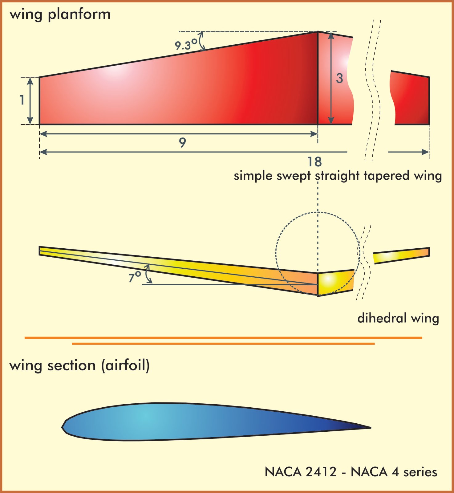
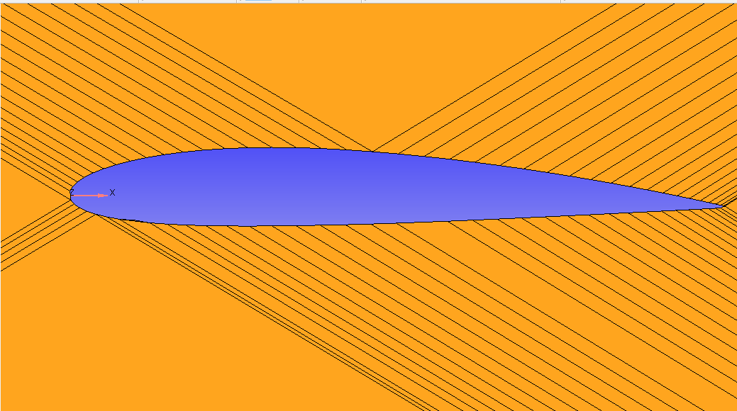
This NACA airfoil series is controlled by 4 digits e.g. NACA 2412, which designate the camber, position of the maximum camber and thickness. If an airfoil number is NACA MPXX e.g. NACA 2412 then: M is the maximum camber divided by 100. In the example M=2 so the camber is 0.02 or 2% of the chord P is the position of the maximum camber divided by 10.
FLOW OVER A NACA 2412 AIRFOIL FOR DIFFERENT ANGLE OF ATTACK WITH TWO
NACA 2412 - NACA 2412 airfoil Plot and print the shape of an airfoil (aerofoil) for your specific chord width and transformation. The dat file data can either be loaded from the airfoil database or your own airfoils which can be entered here and they will appear in the list of airfoils in the form below.

NACA 2412 with 4 Degree Flap Deflection. The NACA 2412 airfoil with a
Wind tunnel tests were conducted on the NASA LS (1)-0421 Mod, NACA 2412 and NASA GA (W)-2 airfoil sections at a Reynolds number of 2.2 x 10 (6) and a Mach number of 0.13. Detailed measurements of flow fields associated with turbulent boundary layers of these airfoils were obtained at pre-stall, near-stall, and post-stall angles of attack.
Flow over an NACA 2412 AIRFOIL Projects SkillLync
Figure 7: NACA 2412 & optimized airfoil using GA . 3.4 Airfoil Shape Optimization With PSO. 10 optimal control po ints are obtained by using the . Particle Swarm Optimization tool of Matlab as.
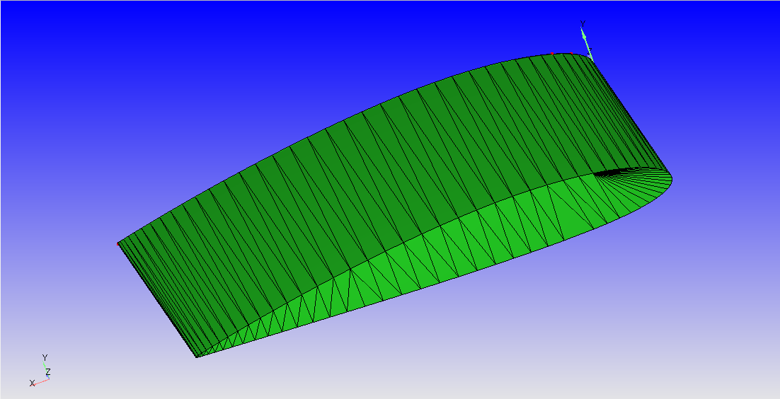
NACA 2412 Airfoil 3D CAD Model Library GrabCAD
Chord. Naca. Naca 4-Series. The calculator below can be used to plot and extract airfoil coordinates for any NACA 4-series airfoil. The chord can be varied and the trailing edge either made sharp or blunt. Use the "Show Coordinates" button to export the resulting coordinate points to a spreadsheet or text editor.
NACA 2412 Airfoil 3D CAD Model Library GrabCAD
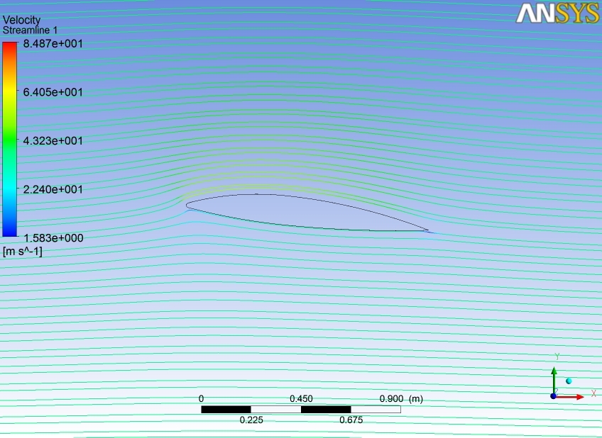
An aerodynamic study of air flow effect around different NACA 2412 airfoil geometries was established using methods of CFD. The main focus of work is to improve efficient engineering procedures.
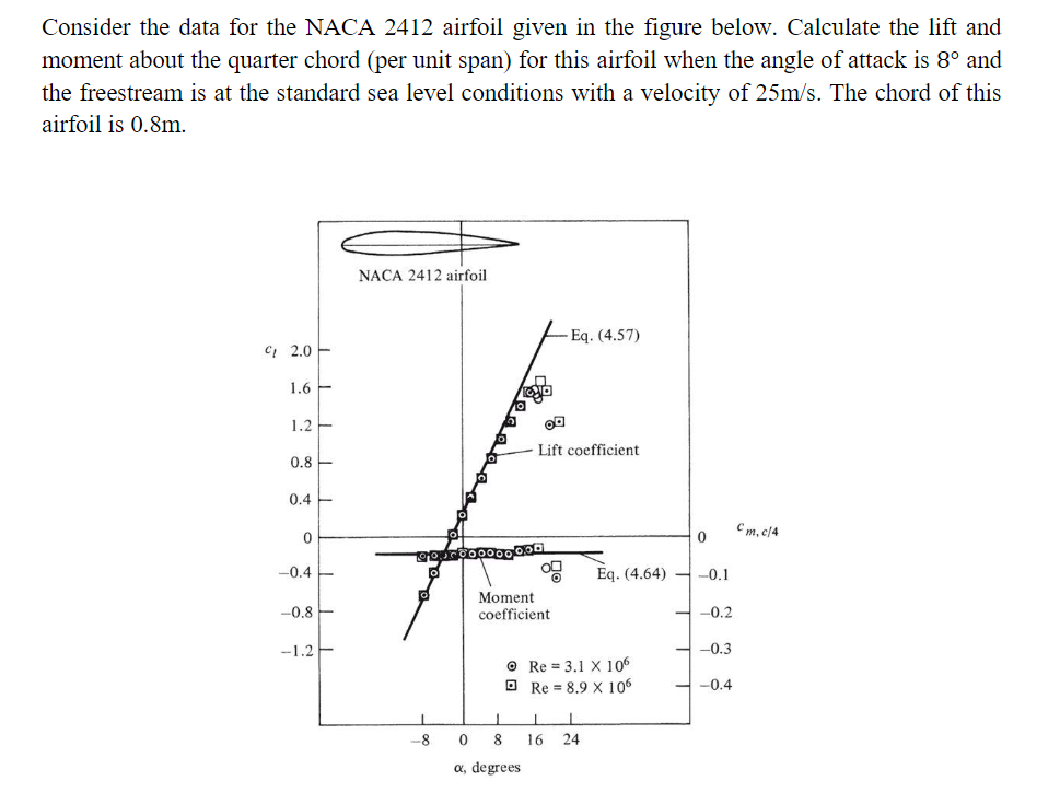
Solved Consider the data for the NACA 2412 airfoil given in
Parser. (naca2412-il) NACA 2412. NACA 2412 airfoil. Max thickness 12% at 30% chord. Max camber 2% at 40% chord. Source UIUC Airfoil Coordinates Database. Source dat file. The dat file is in Selig format.
For the NACA 2412 airfoil, whose aerodynamic
The NACA 2412 aerofoil is ideally suited to any environment where easily maintaining accurate speeds is important. An aircraft with a NACA 2412 aerofoil operating at the middle of its envelope will change speed promptly, reliably and accurately after a power change.

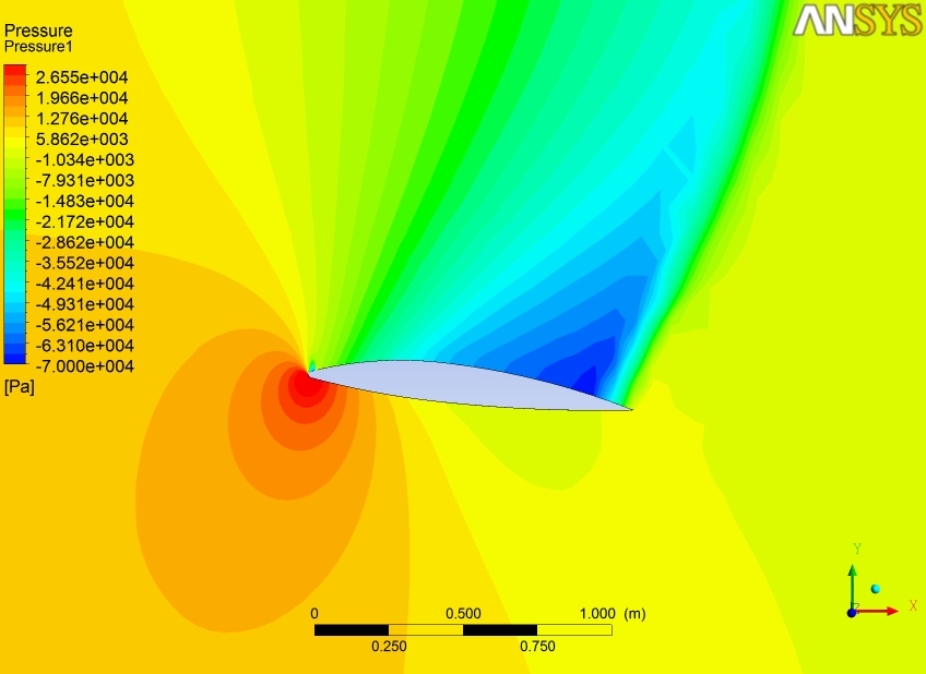
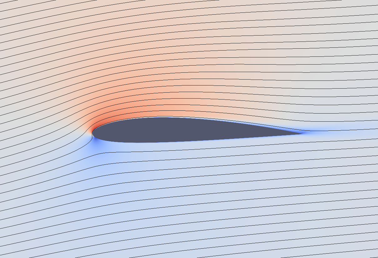
Simulation of Pressure around NACA 2412 Airfoil [8] Download
In this project, we selected a NACA 2412 slow-speed Airfoil with maximum thickness 12% (at 30% chord line) from the leading edge, and maximum camber 2% at 40% chord line. This airfoil is.

Airfoil geometry and camber line for the NACA 2412 airfoil without flap
the airfoil in the direction opposite to the deflection.Various airfoils serve different flight regimes. When an airfoil or any wing moves through air, the flow of air splits up and passes above and below the airfoil. Figure1: Nomenclature of Airfoil Airfoil design is a major facet of aerodynamics.

TOPT Airfoil NACA 2412 Best Cl CFD Optimization YouTube
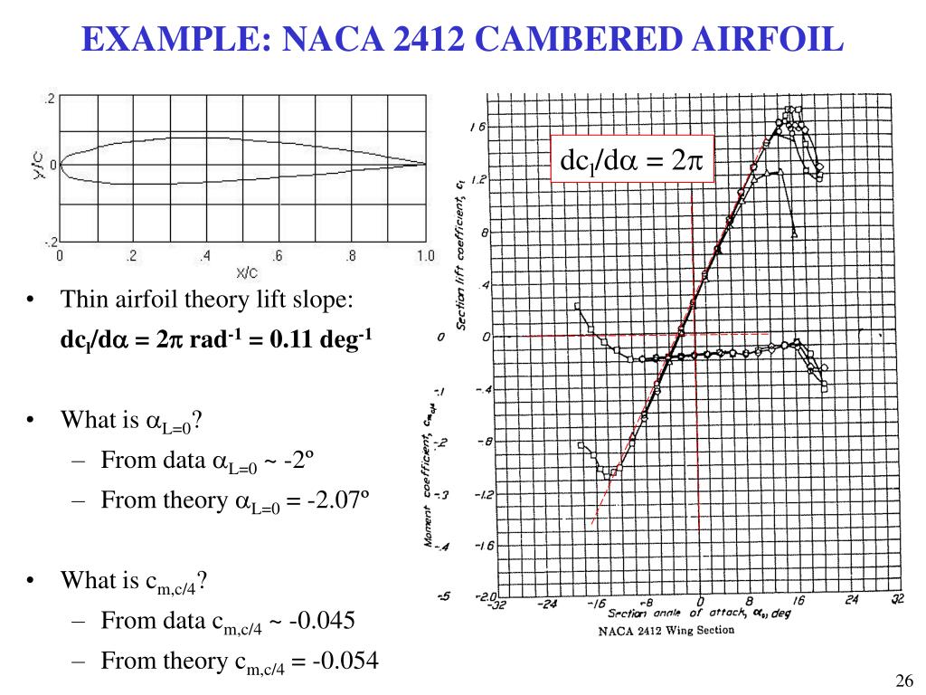
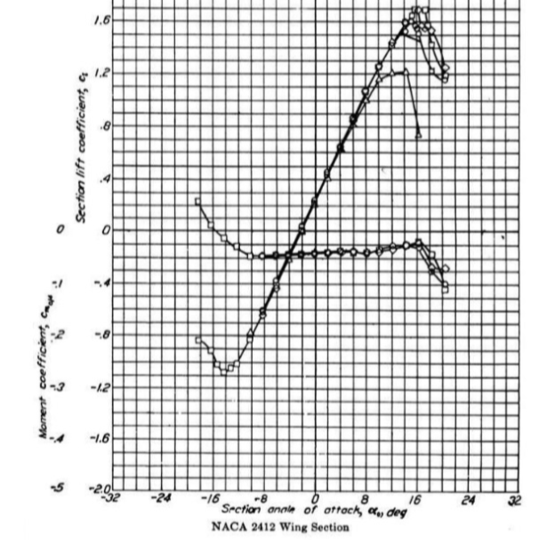
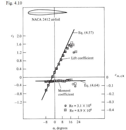
Figure A-2 gives similar data for the NACA 2412 airfoil, another 12% thick shape but one with camber. Note that the lift coefficient at zero angle of attack is no longer zero but is approximately 0.25 and the zero lift angle of attack is now minus two degrees, showing the effects of adding 2% camber to a 12% thick airfoil.
GitHub traviscarrigan/OpenFOAMNACA2412 OpenFOAM case for simulating
Discussions on several airfoils used for blade designing can be found in numerous literatures. Some of the most widely used airfoils are NACA4412 and NACA2412 from National Advisory Committee for Aeronautics, SG6043 from Selig-Giguere and SD7062 from Selig-Donovan group. It is known that lift force provides rotational velocity to the WT.